
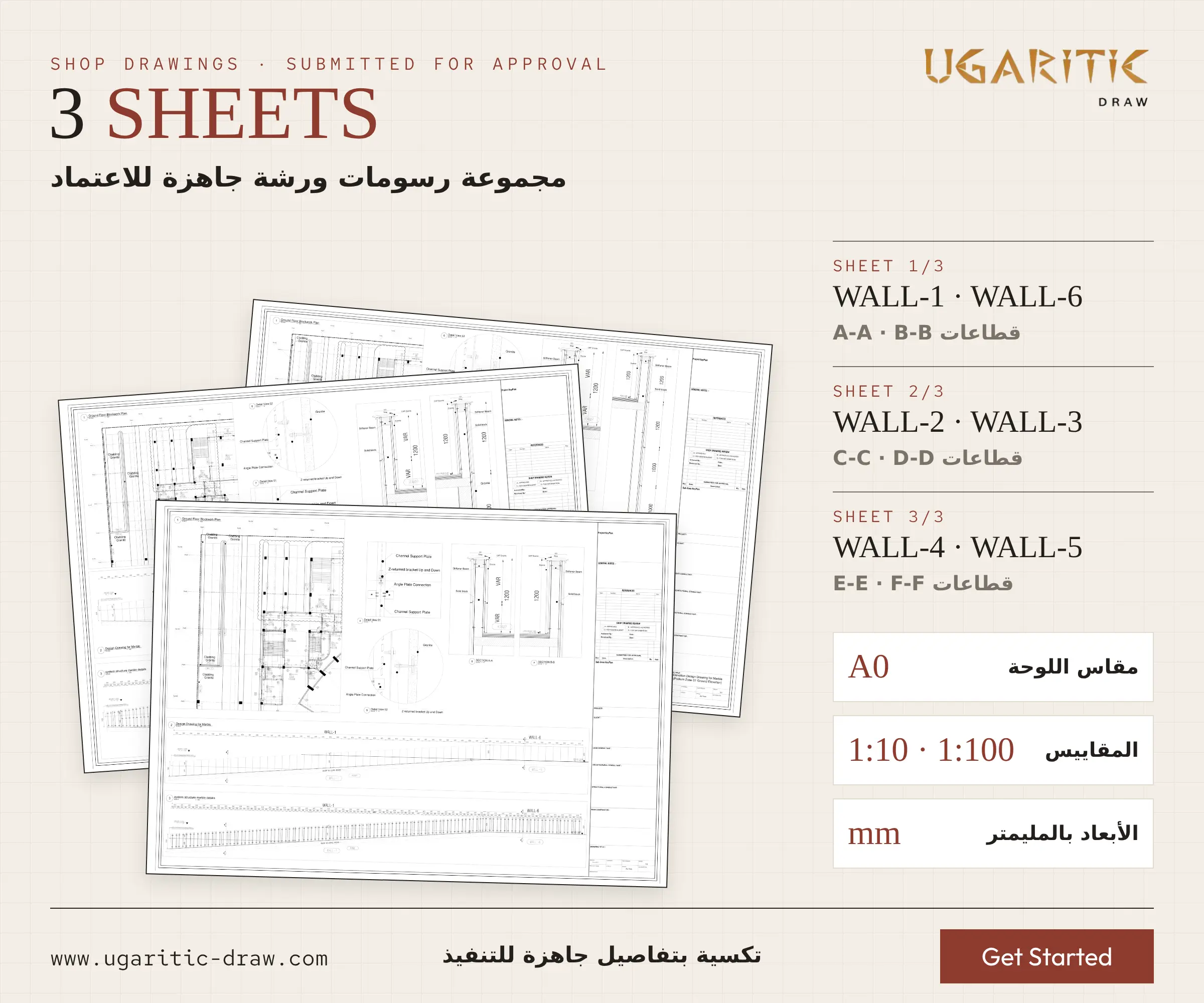
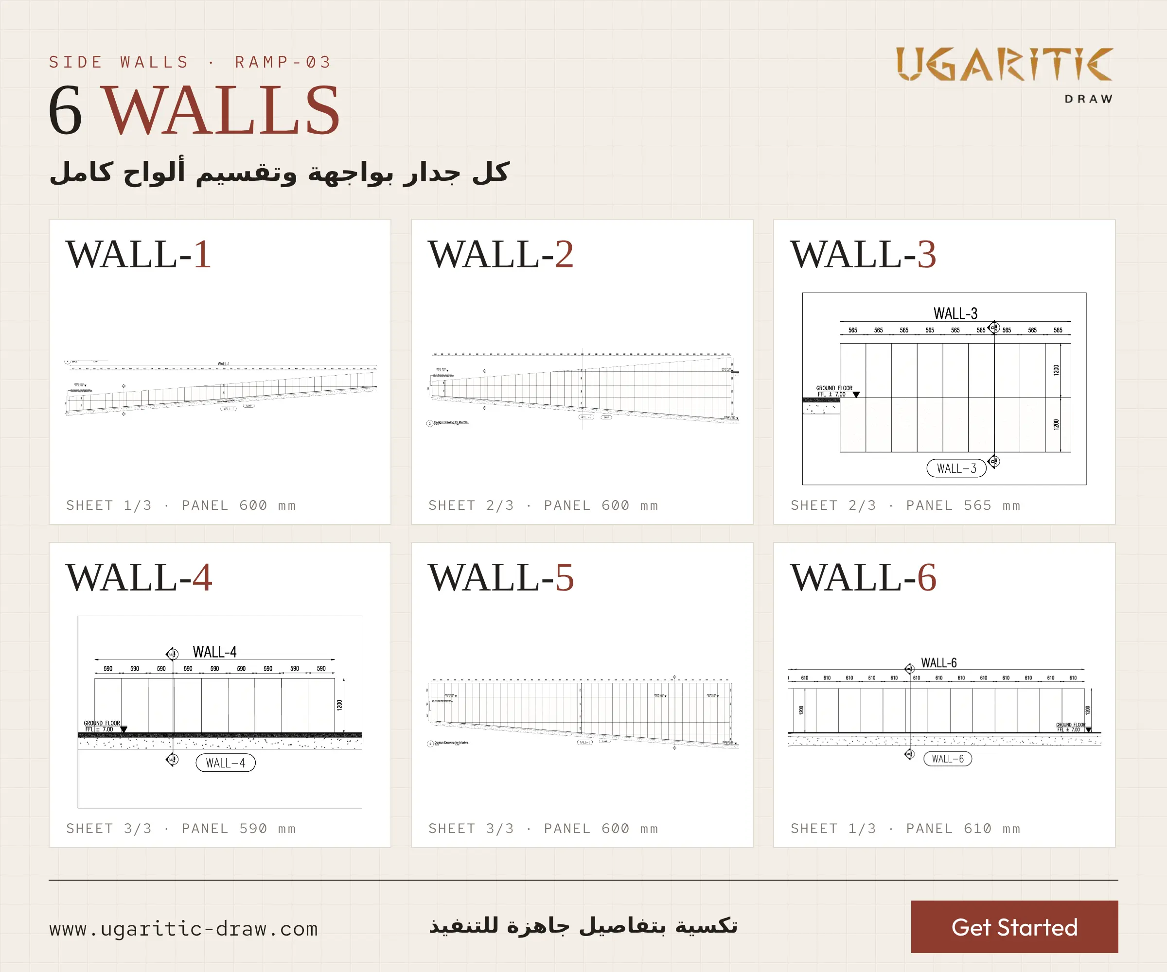
A complete set of elevation and shop drawings for the granite cladding of the six side walls along RAMP-03 (Podium Zone 01, ground elevation). Every wall is drawn twice: a design elevation showing the panel layout as it follows the ramp slope, and a support-structure elevation showing every vertical member behind the stone.
What's inside
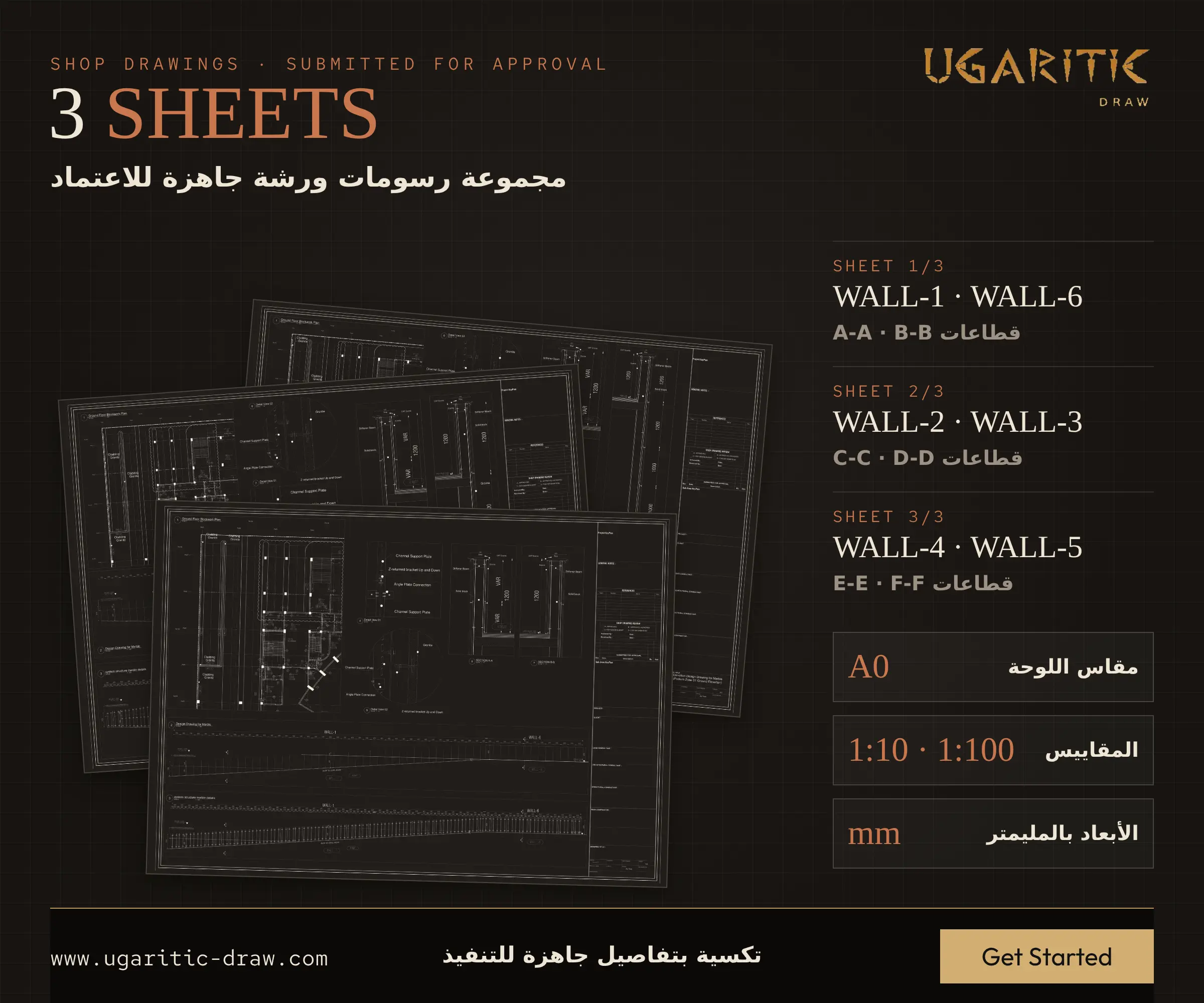
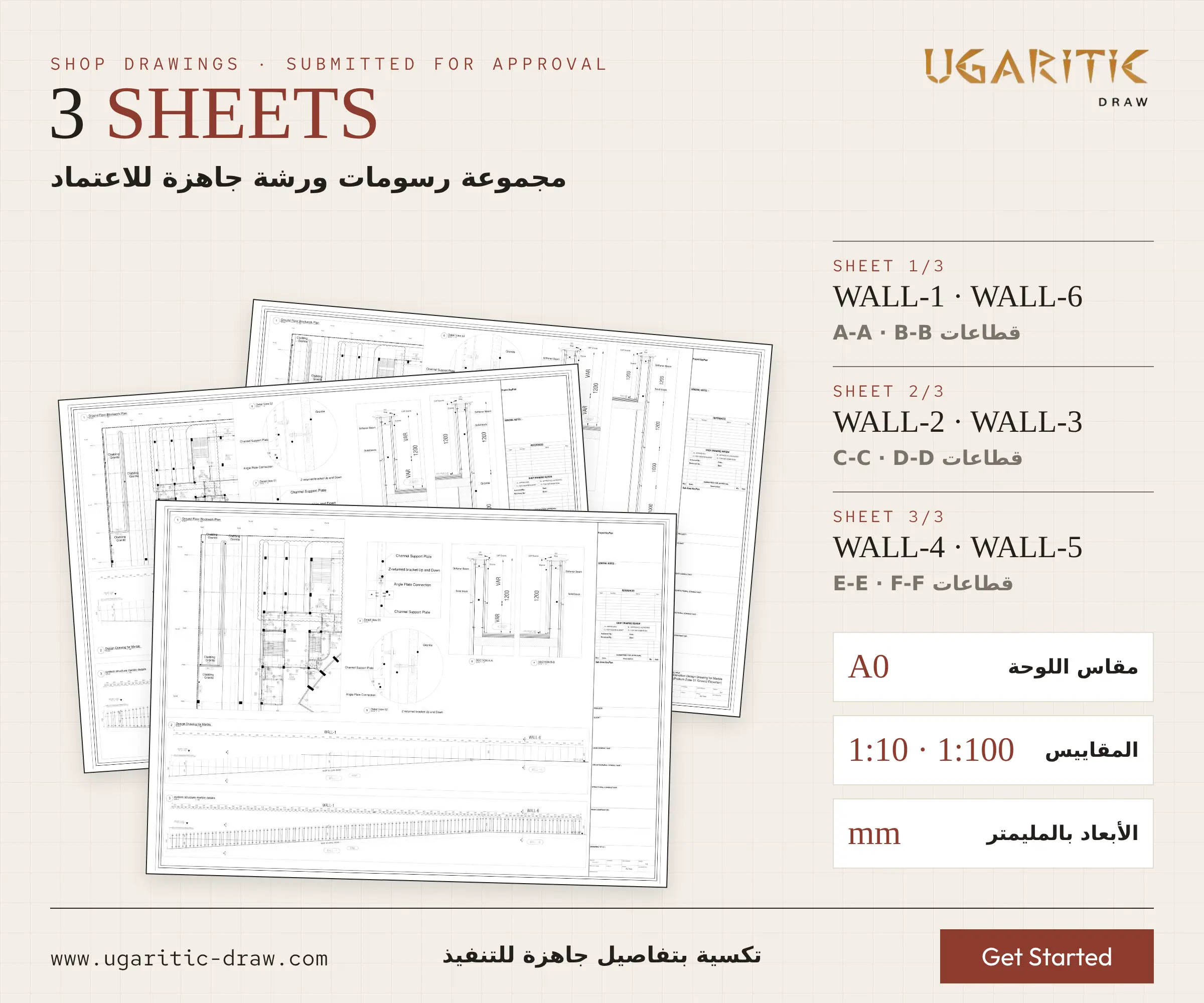
- 3 sheets (A0): Sheet 1 covers WALL-1 and WALL-6, Sheet 2 covers WALL-2 and WALL-3, and Sheet 3 covers WALL-4 and WALL-5, each with the ground floor blockwork plan for location.
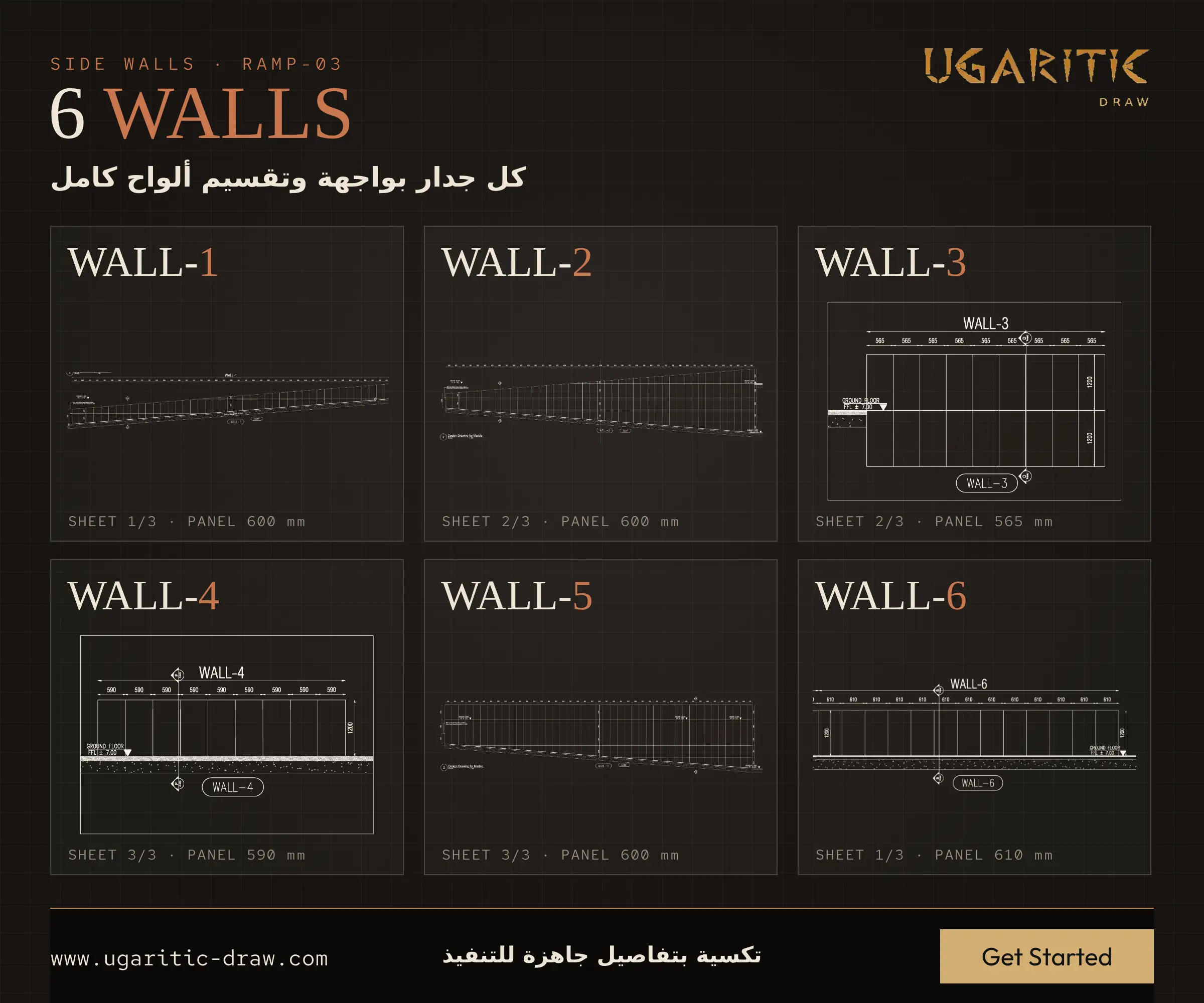
- 6 walls: every wall has a full panel layout with dimensions. Panels are 600 mm wide on WALL-1, 2 and 5, 565 mm on WALL-3, 590 mm on WALL-4 and 610 mm on WALL-6, in courses 1200 mm high.
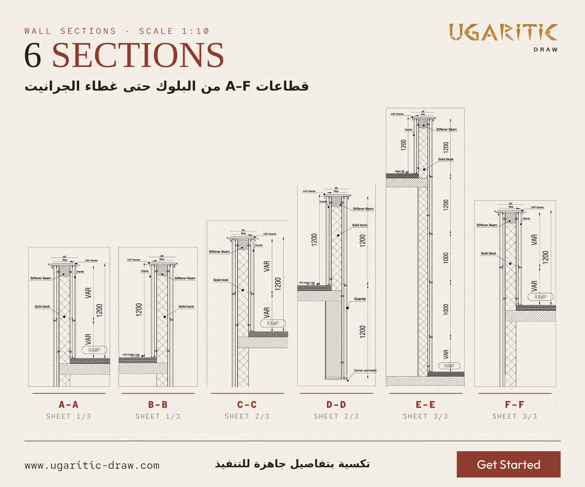
- 6 sections (A-A to F-F) at 1:10: they show the solid block wall, stiffener beam and column, granite cladding, and the sloped cap granite (600 mm), with variable heights along the ramp.
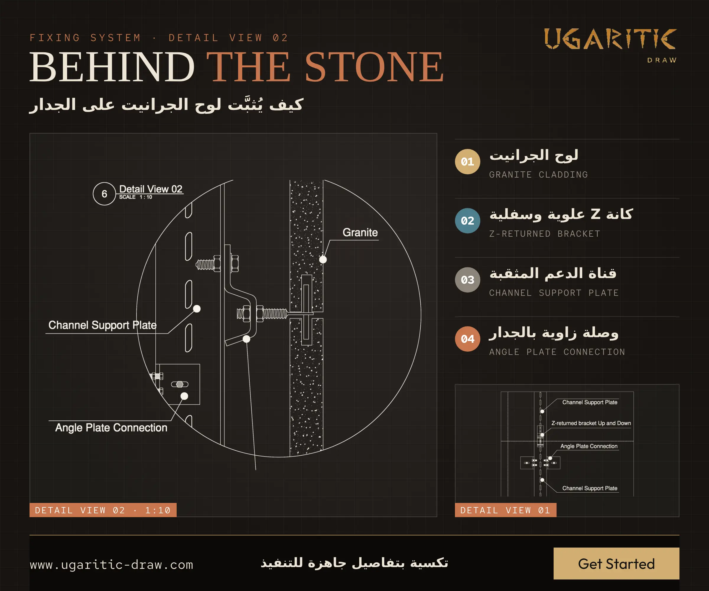
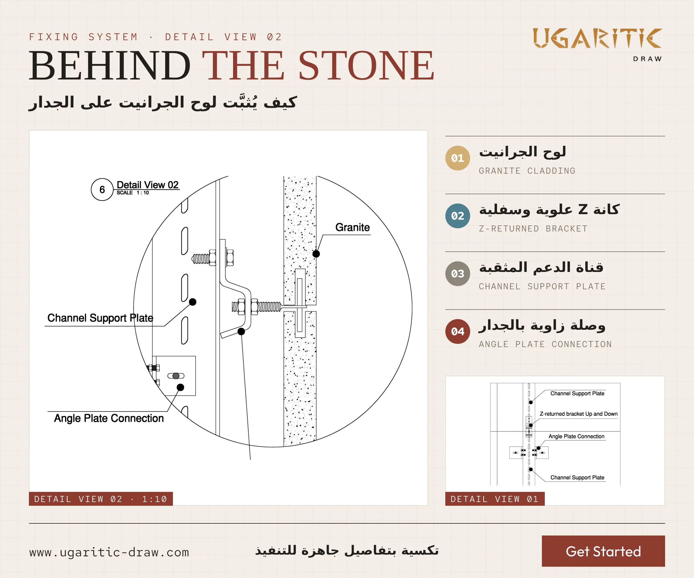
- Fixing details at 1:10: Detail View 01 and 02 show the perforated channel support plate, the Z-returned brackets (up and down), the angle plate connection to the wall, and the corner connection where walls meet.
- Shop drawing review table for consultant approval.
Why it matters
The cladding is built from six coordinated parts, from the solid block to the cap granite, and each one is drawn and dimensioned. All dimensions are in millimetres, at scales of 1:10 and 1:100, so the drawings can be built directly on site with no guesswork for the cladding contractor.