

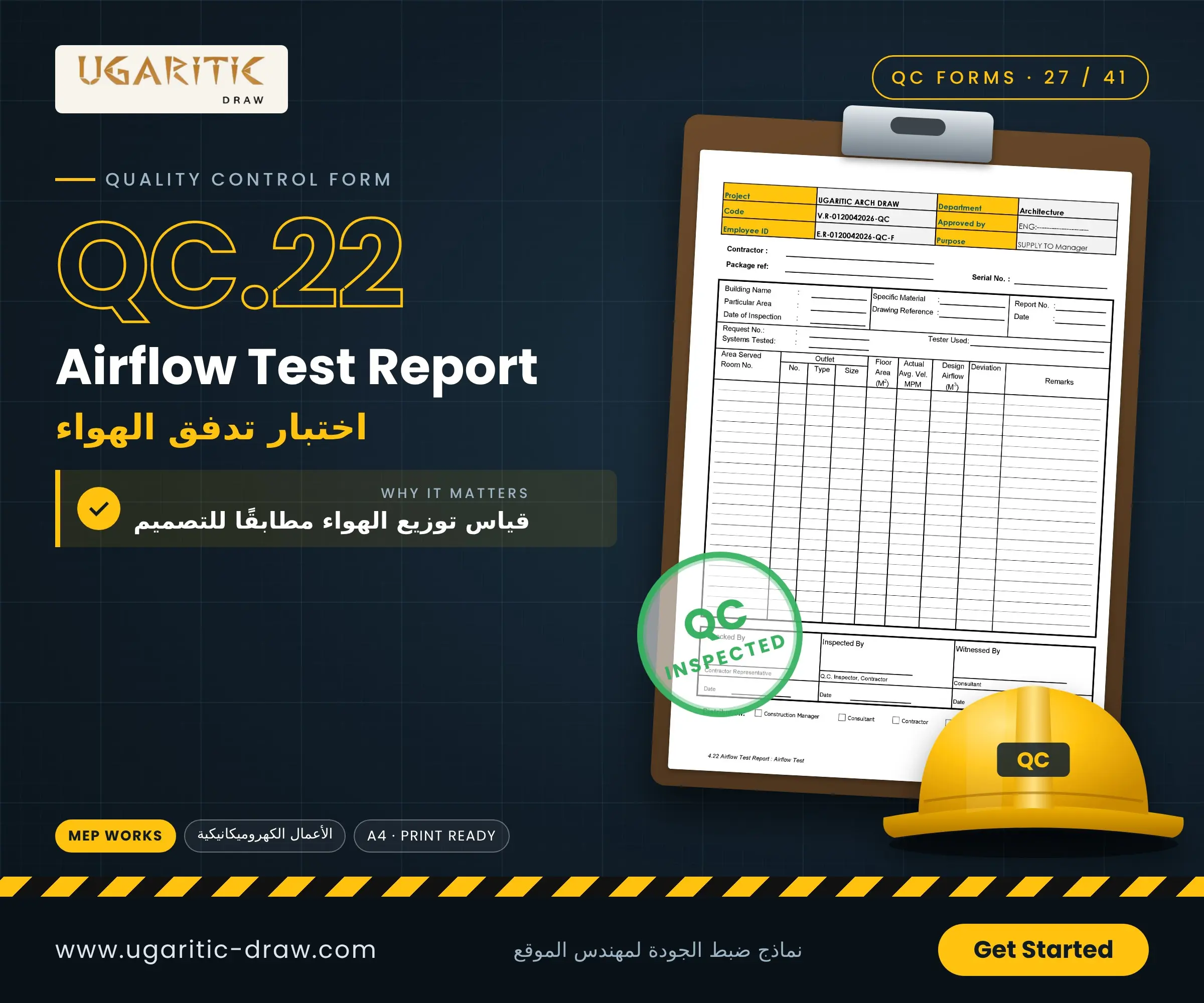
1. Brief Description of the Report
The document is a standardized technical data ledger structured to record field measurements of air velocity and volume at individual terminal outlets (such as diffusers or grilles). It consists of the following key sections:
- Site Reference & Instrumentation Data: Fields to record the Building Name, Particular Area under evaluation, Inspection Date, Specified Material, approved Drawing Reference, Request Number (Request No.), and the specific calibration instrument utilized (Tester Used).
- Airflow Field Data Matrix (The Core Table): A comprehensive grid featuring the following functional analytical columns:
- Area Served / Room No.: To pinpoint the exact spatial location of the test.
- Outlet (No., Type, Size): To log the specific air terminal index number, its mechanical type (e.g., square diffuser, linear slot grille), and its physical dimensions.
- Floor Area (M²): The total square-meter footprint of the room being evaluated.
- Actual Avg. Vel. MPM: The field-measured actual average air velocity recorded in Meters Per Minute.
- Actual Airflow (M³): The calculated or directly measured actual volume of air flowing into the space.
- Design Airflow (M³): The required target air volume specified by the approved engineering design.
- Deviation: The absolute value or percentage gap between the actual field delivery and the target design parameters.
- Remarks: Space to note specific balancing adjustments made to volume control dampers (VCDs).
- Multi-Party Sign-Off Block: Formal authentication fields requiring individual validation signatures and dates from the Contractor Representative, Q.C. Inspector, and Consultant acting as an official witness (Witnessed By).
2. Purpose of the Report
The primary purpose of this test report is to facilitate systematic Air Balancing across the ventilation network, ensuring an equitable, engineered distribution of conditioned or fresh air to all spaces within the building. Its core objectives include:
- Achieving Occupant Thermal Comfort: Verifying that every room or office receives an air volume proportional to its size and calculated heat load, preventing scenarios where some rooms are over-cooled while adjacent spaces remain warm due to poor flow distribution.
- Quantifying and Rectifying System Deviations: Identifying discrepancies where actual airflow falls short of or exceeds the Design Airflow, prompting technicians to manually throttle or open volume control dampers until field readings match design thresholds within standard acceptable tolerances.
- Validating Fan and Air Handling Unit (AHU) Performance: Legally proving that the mechanical equipment is successfully delivering its total rated air volume and that the distribution ductwork is not bottlenecking or wasting that volume.
- Handover & Commissioning Records Retention (Distribution): Preparing a binding technical performance log distributed to the Construction Manager, Consultant, and Contractor to be filed inside the final project handover files.